
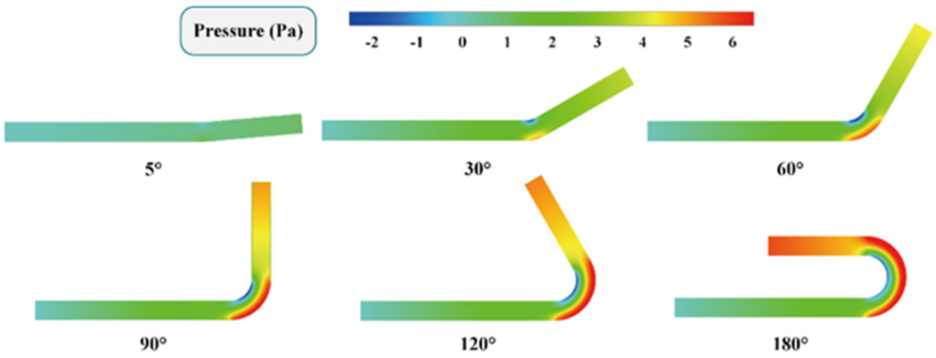
U-bend radii play a critical role in the performance of heat exchangers, piping systems, and HVAC applications, yet they often introduce complex challenges related to flow distribution and pressure drop. When fluid passes through a U-bend, especially one with a tight radius, it experiences centrifugal forces that can cause uneven velocity profiles and secondary flows. This maldistribution not only reduces thermal efficiency in heat exchangers but can also accelerate wear and corrosion in piping systems due to localized turbulence. Engineers must carefully balance compact design requirements with hydraulic performance—opting for larger bend radii where possible to minimize flow separation and ensure uniform fluid distribution across parallel channels.
Recent advancements in computational fluid dynamics (CFD) have enabled more precise modeling of U-bend effects, allowing designers to predict and mitigate flow imbalances before physical prototyping. Additionally, innovations like flow straighteners, guide vanes, or asymmetric manifold designs are being integrated upstream of U-bends to homogenize velocity profiles. In industries such as chemical processing, power generation, and refrigeration, optimizing U-bend geometry is now seen as a key lever for improving system efficiency and reducing operational costs. High-performance applications—like compact plate-fin or microchannel heat exchangers—are particularly sensitive to these nuances, making bend radius selection a strategic decision rather than a mere geometric constraint.
For professionals working on thermal-fluid systems, understanding the interplay between U-bend radii and flow distribution is essential for meeting energy efficiency standards and sustainability goals. With increasing emphasis on green engineering and reduced carbon footprints, even minor improvements in flow uniformity can translate into significant energy savings over a system’s lifecycle. By combining empirical testing with digital twin simulations, modern engineers are better equipped than ever to tackle these hydraulic challenges head-on—ensuring reliability, performance, and compliance in demanding industrial environments.
U-bends are critical components in piping systems, often used to change flow direction while minimizing pressure drops. However, improper U-bend radii can lead to significant flow distribution issues, including turbulence, uneven velocity profiles, and increased energy losses. A smaller bend radius may reduce space requirements but can cause higher shear stress and flow separation, leading to premature wear and inefficiencies. Conversely, a larger radius improves flow characteristics but may not always be feasible due to spatial constraints. Engineers must strike a balance between hydraulic performance and practical installation requirements, making U-bend design a key challenge in fluid systems. Flow distribution in U-bends is further complicated by factors like fluid viscosity, pipe diameter, and Reynolds number. Laminar flows tend to maintain smoother profiles, while turbulent flows exacerbate uneven distribution, leading to hotspots or dead zones. Computational Fluid Dynamics (CFD) simulations are often employed to optimize U-bend geometries, ensuring uniform flow and minimizing energy losses.