
Sizing a fin tube evaporator coil starts with an accurate cooling load—total BTU/hr (or kW) needed at design conditions—broken into sensible and latent components, because humidity removal drives coil selection just as much as dry-bulb temperature. Use the space’s entering air conditions (dry-bulb and wet-bulb), desired leaving air temperature, target supply air humidity/dew point, and required airflow (CFM) to define the job. From there, select a coil face area that keeps face velocity in the sweet spot (typically 400–500 FPM for comfort cooling; lower for high-latent or low-temperature rooms) to control pressure drop, condensate carryover, and bypass factor. Choose rows and fin density (FPI) to hit the needed log mean temperature difference (LMTD) and UA, remembering that more rows and higher FPI boost heat transfer but increase air-side pressure drop and fouling risk. Match tube diameter (e.g., 3/8″ or 1/2″), tube spacing, and circuiting to maintain proper refrigerant velocity for oil return while minimizing refrigerant pressure drop; undersized circuits starve the coil, oversized circuits hurt superheat control.
Next, set your evaporating temperature (SST) and coil TD/approach relative to entering air conditions and the refrigerant you’re using (e.g., R410A, R407C, R134a, R404A, R448A). Lower SSTs improve latent removal but increase compressor power and frost risk; for comfort cooling, a coil TD around 35–45 °F (19–25 K) is common, while low-temp applications may run colder with planned defrost. Validate superheat targets at the outlet for stable expansion valve control and confirm subcooling upstream for feed quality. Always check external static pressure impacts: higher coil air-side ΔP demands a stronger fan and raises energy use, so balance rows/FPI against fan horsepower. Include altitude correction (air density) when applicable, and apply fouling factors plus a 10–15% safety margin so capacity holds after months of operation, not just on day one.
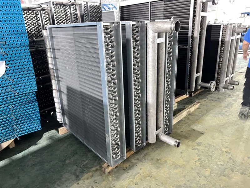
Material and durability choices affect life-cycle performance. Copper tubes with aluminum fins deliver strong heat transfer at low cost; epoxy or phenolic-coated fins resist corrosion in coastal, food, or chemical environments; stainless steel or cupronickel may be justified for aggressive atmospheres; and hydrophilic fins speed condensate shedding to reduce re-evaporation and improve sensible capacity. If the application is cold storage or freezers, consider wider fin spacing, designed defrost cycles, and drain pan heat to manage frost and maintain airflow. Finally, verify the selection with coil software or manufacturer data: confirm capacity at design CFM, air- and refrigerant-side pressure drops, leaving air conditions, sound/energy impact, and physical fit (coil length, height, header side, connection size/orientation). Properly sized, a fin tube evaporator coil delivers stable temperature and humidity, lower compressor run time, and optimized energy efficiency across real-world operating conditions.