The Engineered Canvas: How Plate Design Dictates GPHE Performance
The heart of a Gasketed Plate Heat Exchanger (GPHE) lies in its meticulously engineered plates, which serve as the primary heat transfer surface. Far from being simple flat sheets, the intricate plate design is the single most critical factor determining the unit’s thermal efficiency, pressure drop characteristics, and overall performance. Each plate is precisely pressed with specific corrugation patterns that create turbulent flow paths, maximizing the interaction between the fluids and the plate material. The thinness of these plates, typically ranging from 0.4 mm to 1.0 mm, minimizes thermal resistance and allows for exceptionally rapid heat transfer. This deliberate design, considering both macro and micro geometries, is what enables GPHEs to achieve compact footprints and high heat transfer coefficients, making them a preferred choice for numerous industrial and commercial applications. Port size, inlet manifold design and plate port geometry control flow distribution across the pack; poor distribution creates dead zones, local bypassing, and reduced effective area. Designers use asymmetric or enhanced port shapes and distribution feeders to equalize velocities and avoid maldistribution when fluids have mismatched viscosities or when multi‑pass arrangements are used. Wide‑gap plates, flow distributors, or engineered port inserts can be specified for particulate or fibrous fluids to keep self‑cleaning traits while preventing clogging—important points under Flow Distribution, Wide Gap Plates and Fouling Resistance in your blog.
The Art of Turbulence: Chevron Patterns and Flow Optimization
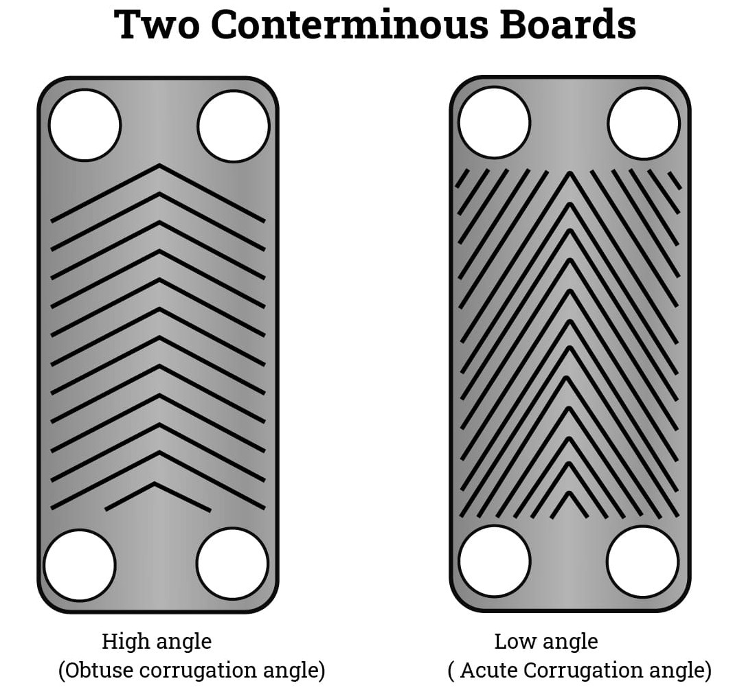
The most common and effective element of plate geometry in GPHEs is the chevron pattern, also known as the herringbone design. These angled corrugations are typically arranged at varying angles (e.g., 30° or 60°) to the main flow direction. When two identical plates are placed together but rotated 180° relative to each other, the intersecting chevron patterns create a complex network of flow channels. This forces the fluids into highly turbulent flow, even at low velocities, continuously breaking up the laminar boundary layers that would otherwise insulate the plate surface. By manipulating the chevron angle, designers can optimize the balance between heat transfer enhancement and allowable pressure drop. Steeper angles (e.g., 60°) generate higher turbulence and thus greater heat transfer but also incur higher pressure losses, while shallower angles (e.g., 30°) offer lower pressure drops suitable for viscous fluids or limited pump head applications. Plate design starts with geometry: corrugation depth, chevron angle and plate amplitude are the primary levers that tune turbulence, heat transfer coefficient, and pressure drop. Steeper chevrons and deeper corrugations increase the convective heat transfer (raising U and UA for a given footprint) but also raise ΔP, so designers choose patterns by balancing thermal duty against pump energy and fouling risk. Mentioning terms like Chevron Angle, Corrugated Plate Pattern, and UA Optimization in your post will help readers quickly grasp why two plates that look similar can perform very differently in practice.
Beyond Standard: Specialized Plates for Diverse Challenges
While chevron plates are ubiquitous, specialized plate designs address unique operational demands. Free-flow plates, characterized by wider gaps and fewer contact points, are specifically designed to handle fluids with high viscosity or particulate matter, such as slurries, wastewater, or pulp. Their open channels prevent clogging and maintain consistent performance in challenging media. Another innovation is the double-wall plate, which features two thin plates pressed together, creating an air gap between them. This design is a critical safety feature for applications where cross-contamination of fluids must be absolutely prevented, such as in pharmaceutical manufacturing or potable water systems. Material selection for plates is also a key design consideration, ranging from standard 316L stainless steel for general applications to exotic alloys like titanium or Hastelloy for highly corrosive environments, ensuring the plate material compatibility with the aggressive fluids while extending the heat exchanger lifespan. Gasket groove style, attachment method and plate material selection affect service life as much as thermal numbers. Clip‑on vs. glued gaskets trade replaceability for migration resistance; gasket material choice (EPDM, FKM, PTFE‑encapsulated) must be matched to CIP chemistry and operating temperature. Plate pack alignment, tie‑bar stiffness and documented tightening torque influence creep, vibration and leak risk—so include Gasket Selection, Plate Pack Modularity and Tightening Procedure when advising operators or procurement teams.