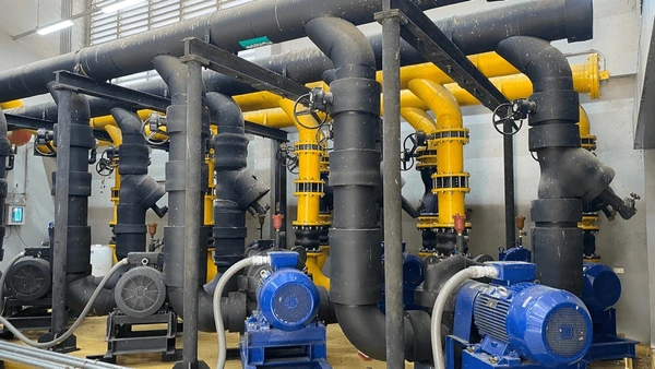
Water Piping and Valves in Water-Cooled Chillers are not merely connectors—they are the lifelines of the entire chilled water system. While the chiller is the heart that generates cooling energy, it is the piping that serves as arteries and valves as regulators, ensuring that this energy reaches every end-use point effectively and efficiently.
The integrity, layout, and automation of the piping and valve system define the reliability, efficiency, and scalability of HVAC and process cooling solutions. A properly engineered water piping and valve system reduces downtime, conserves energy, facilitates maintenance, and enables smart control.
Purpose and Flow Overview in Water-Cooled Chillers
Chilled Water Loop
- From Evaporator to Load: Chilled water is pumped to air handling units (AHUs), fan coil units (FCUs), or process equipment.
- Return to Chiller: The now warmed water returns to the chiller evaporator to be cooled again.
Condenser Water Loop
- From Condenser to Cooling Tower: Heat-absorbed water exits the condenser.
- From Cooling Tower to Condenser: Cooled water re-enters the condenser.
A correct balance between temperature, pressure, and flow rate across these loops is critical to maintain the Coefficient of Performance (COP) and overall energy efficiency of the chiller plant.
Detailed Valve Types and Application
Every valve in the system must be carefully chosen to balance functionality, durability, and system control logic.
Isolation Valves
- Function: Shut off flow for maintenance or emergencies.
- Common Types:
- Ball Valves: Quick-action for small diameters
- Butterfly Valves: Lightweight, large bore applications
- Gate Valves: Slow acting but ideal for full flow
Balancing Valves
- Function: Equalize water distribution to different branches.
- Types:
- Manual: Adjusted during system commissioning.
- Automatic: Pressure-responsive; no need for frequent tuning.
- PICVs: Integrate balancing and modulating control—ideal for smart HVAC systems.
Check Valves
- Function: Prevent reverse flow that could damage pumps or chillers.
- Considerations:
- Must have a low cracking pressure.
- Should be accessible for periodic inspection.
Control Valves
- Function: Modulate flow to maintain temperature or pressure setpoints.
- Actuation:
- Manual
- Electric (modulating with BMS)
- Pneumatic (used in industrial systems)
Piping System Layouts
A poor layout can reduce system performance by 20–40% due to pressure drops and imbalance. Common configurations include:
Direct Return System
- Shortest path is not always the best.
- Flow imbalance may occur unless all branches are carefully balanced.
Reverse Return System
- Naturally balances flow without elaborate balancing valves.
- Slightly higher material and labor cost due to extended pipe routing.
Primary-Secondary Systems
- Allows for variable system flow while maintaining constant chiller flow.
- Prevents surging and improves efficiency in multiple chiller systems.
Decoupled Systems with Bypass Loops
- Avoids excessive flow through chillers when demand is low.
- Includes bypass valves and control logic for optimal operation.
Flow Design and Engineering Best Practices
Flow Rate Calculation
- Overdesign increases capital cost.
- Undersizing leads to pressure drop, low velocity, poor heat transfer.
- Formula:
Flow Rate (LPM) = Q (kW) × 14.3 / ΔT (°C)
Expansion Compensation
- Long piping runs require expansion loops or bellows to prevent stress fractures.
Support & Anchoring
- Pipe supports every 3–5 feet.
- Anchors and guides must allow axial movement.
Environmental and Application Relevance
Industrial Applications:
- Injection molding, dairy chillers, chemical plants—require precise water control.
- Flow imbalance can affect product quality and equipment lifespan.
Commercial HVAC:
- Hospitals, IT parks, malls depend on uninterrupted chilled water.
- Smart valves reduce manual oversight and improve uptime.
Pharmaceutical / Food:
- Sanitary design valves like diaphragm or stainless steel ball valves are used.
- Water quality and pressure must comply with safety regulations.
Energy Efficiency Through Valve and Piping Engineering
- Pressure drops across poor valve/piping layouts can increase pump energy usage.
- Insulation alone can prevent up to 30% of energy loss in large buildings.
- VFDs (Variable Frequency Drives) on pumps in tandem with control valves help adapt flow to real-time cooling load, saving up to 40% on energy.
- Dynamic balancing valves reduce the need for oversized pumps and reduce flow fluctuation.
Water Piping and Valves in Water-Cooled Chillers are not just mechanical accessories—they are the command pathways for an entire cooling system’s success. Precision in piping layout and valve selection can drastically improve system reliability, thermal efficiency, and ease of operation. A professionally engineered water loop minimizes operational expenses, boosts chiller life, and enables intelligent automation.
As HVAC systems evolve toward smarter and more sustainable operations, the strategic integration of piping and valve infrastructure becomes a central piece in delivering both performance and compliance with energy standards. Whether you’re building a new system or retrofitting an existing one, attention to detail in piping and valve design pays for itself in operational excellence.

