In modern industrial environments, hydraulic systems are essential for driving heavy machinery, maintaining mechanical operations, and delivering high-pressure power. However, these systems generate a considerable amount of heat during operation, especially when used continuously in machines like injection molding units, CNC machines, or presses.
If the hydraulic oil temperature rises above its optimal level, it can result in:
- Oil viscosity reduction
- Seal damage
- Component wear
- System inefficiency
- Thermal degradation of the fluid
This is where a Hydraulic Oil Chiller plays a crucial role. It ensures that the oil temperature remains within a safe and efficient range, protecting equipment and extending lifespan.
Heat Build-up in the Hydraulic Oil
As machinery operates, hydraulic oil undergoes:
- Friction between internal components
- Pressure drops across valves and orifices
- Turbulence in the fluid pathways
- Mechanical resistance in actuators
This frictional and mechanical energy is converted into heat, raising the oil temperature. Without temperature regulation, this heat can exceed 70°C, which is harmful to most hydraulic fluids.
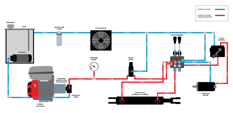
Oil Circulation: Extracting Hot Oil
- The hot oil is diverted from the hydraulic reservoir or return line using a dedicated oil pump.
- The chiller draws the oil through inlet ports, generally without disturbing the main hydraulic circuit, making it suitable for retrofitting and side-loop installations.
- The oil enters the heat exchanger unit.
Heat Exchanger Mechanism: Oil Meets Refrigerant
There are two common types of heat exchangers used in oil chillers:
- Shell and Tube
- Brazed Plate
The hot oil passes through the tube side (or oil channel) while the refrigerant flows in the counter-direction on the shell side or plate gaps.
- As the refrigerant absorbs heat from the oil, it undergoes phase change from liquid to vapor.
- The cooled oil exits the exchanger and is returned to the hydraulic reservoir.
Refrigeration Cycle: The Core of Cooling
Now that the refrigerant has absorbed heat, the cooling cycle begins:
Evaporator Stage
- The heat exchanger itself functions as the evaporator.
- The low-pressure liquid refrigerant absorbs heat and turns into vapor.
Compressor Stage
- The compressor (scroll, rotary, or reciprocating type) sucks the low-pressure vapor and compresses it into high-pressure vapor.
- This high-pressure vapor carries the extracted heat.
Condenser Stage
- The vapor enters the condenser (air-cooled with fins/fans or water-cooled).
- Here, it releases heat to the surrounding air or water.
- The refrigerant turns back into a high-pressure liquid.
Expansion Valve Stage
- This high-pressure liquid passes through an expansion valve or capillary tube, reducing its pressure.
- The cold, low-pressure refrigerant re-enters the evaporator to start the cycle again.
Integrated Control and Safety Systems
Hydraulic oil chillers are equipped with advanced automation features:
- Digital temperature controllers to maintain set oil temperatures.
- Flow switches and pressure sensors to ensure oil is moving through the system.
- Refrigerant safety cutoffs to prevent overload.
- Alarms for high/low temperature, refrigerant leakage, oil flow failure, or compressor fault.
- Variable Frequency Drives (VFDs) to reduce energy use during partial load conditions.
The hydraulic oil chiller is not just a cooling device—it’s an essential safeguard for modern hydraulic systems. Its working principle combines fluid dynamics, thermodynamics, and precision refrigeration to maintain hydraulic oil at safe, stable temperatures. This ensures longer system life, lower maintenance costs, and enhanced machine accuracy.
As industries continue to demand higher efficiency and automation, hydraulic oil chillers are evolving into smarter, more compact, and energy-efficient thermal management systems, truly becoming the silent protectors of industrial reliability.